Workmanship

Orders with Xometry will meet the minimum workmanship standards outlined below (as applicable to the process). If your project requires a level of workmanship that goes beyond the standards listed below, please clearly list the requirement in your engineering drawings, purchase orders, or specifications. 


Finished Surfaces Cosmetics

  • Paint coverage on surfaces will be uniform, including adjacent materials of assemblies.
  • Finished surfaces will be free of defects, including chips, scrapes, or other damage.
  • Parts made with Sheet Cutting and Sheet Metal Fabrication have different cosmetics standards. Please see their sections below for details.

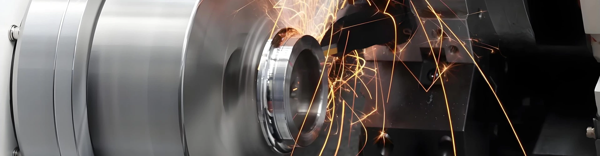
Mill Steps, Tooling, and Chatter

  • Tool marks on as-milled surfaces will be free of defects, including burrs, chatter, tool gauges, and will meet surface roughness specifications.
  • Indicated critical surfaces will be free of mill steps and marks across the entire surface. 
  • Milled surfaces will meet surface roughness specifications. 

Chips, Burrs, and Sharp Edges

  • All exposed edges will be free of burrs, sharp edges, and metal slivers.*
  • *Parts made with Sheet Cutting are not deburred unless specified through a selected finish.

Foreign Object Debris (FOD) 

  • Surfaces will be free of cutting fluid, metal chips, foreign objects, and other debris.

Threads

  • Threads will be fully formed and cut to specified size and class indicated in provided drawings.
  • Threads will be free of defects, notable damage, and contamination. 

Plated Surfaces

  • Plated surfaces will be uniform, including adjacent surfaces of assemblies. 
  • Plated surfaces will be free of machining marks, scratches, pits, protrusions, or visible bare metal. 
  • Some minor defects may be permissible in certain situations if they do not compromise the protective finish.

Weld Joints

  • Weld joints are performed as indicated in the customer-provided drawing.
  • Welds without specific requirements are cleaned to remove slag or other surface contamination. 
  • Weld joints will not be painted until the welding has been completed and the weld has passed inspection. 

Countersinks

  • Countersinks shall be round and made to print specifications and allow the proper designed fit with the mating screw. 
  • Countersinks will be free of burrs, chatter, or other tooling defects. 

Painted Surfaces

  • Painted surfaces shall be consistent and continuous in the finish.  
  • Painted surfaces shall be free of visible machining marks, scratches, abrasions, dust particles, fisheyes, orange peel, or bare metal. 
  • Painted surfaces should be reviewed against this standard at a distance of 18" at 1X magnification. 

Supported Surfaces (Additive Manufacturing / 3D Printing)

  • Unless otherwise specified, Xometry or Xometry Partner additive manufacturing technicians will determine the part's support orientation to best accommodate product design, cost, and the mitigation of support structures.
  • Processes that require supporting structures may leave small vestiges on the part where the supports were attached.
  • Depending on the process, support vestiges can be mitigated with secondary processes, such as sanding.

CNC Machining and Turning

  • For features of size (Length, width, height, diameter) and location (position, concentricity, symmetry) +/- .005” (metals) or +/- .010 (plastics and composites) following ISO 2768 unless otherwise specified.
  • As machined surface finish is 125 Ra or better. Machine tool marks may leave a swirl-like pattern.
  • Sharp edges will be broken and deburred by default. Critical edges that must be left sharp should be noted and specified on a print.
  • Clear or transparent plastics will be matte or have translucent swirl marks on any machined face. Bead blasting will leave a frosted finish on clear plastics.
  • Xometry cannot guarantee tolerances on foam or similar compressible materials.
  • General tolerances for orientation and form features are outlined below unless we have agreed to other tolerances in your Quote. These features include parallelism, perpendicularity, cylindricity, concentricity, flatness, circularity, and straightness.

CNC Orientation and Form General Tolerances for Metals

Table: Parallelism, Perpendicularity, Cylindricity, Circularity, Concentricity, Flatness, and Straightness over Part Length

Part Length Orientation and Form Tolerance (inch) Angularity Tolerance (degree)

0 to 12"

.005"

0.5°

12" to 24"

.010"

0.5°

24" - 36"

1/64" (.016")

36" - 60"

1/32" (.031")

Over 60"

1/16" (.063")

Form tolerances apply to metal machined components. Plastic and composite materials are typically double the tolerance amount for metals.

Die Casting

  • Typical mold machined tolerances are +/- .010" when machining the mold and an additional +/- .001" per in. when calculating shrink rate.
  • Tighter as-molded tolerances can be requested and may increase the cost of tooling. Additionally, many tight tolerances require the mold to be manufactured, sampled, and groomed. Xometry will mill to a steel-safe condition on critical features.
  • Critical toleranced features and surface finishes may require post-machining and should be noted in the quote prior to order. Post-machined features will follow Xometry’s CNC manufacturing standards.
  • Xometry will produce die cast components according to the net-shape (as-cast) model provided by the customer. These models must contain appropriate material for any additional post-processing efforts, such as post-machining. It is recommended to provide the as-cast 3D model as well as the final model with any accompanying technical drawings.
  • Part-to-part repeatability is typically under +/- .004".
  • As-cast surface finish is typically 64 μin. The standard finish for die-casting is as-cast and cannot guarantee a specific Ra value without additional processing.
  • The lead time is for the first article shipment (T1 shipment). The remaining production time is confirmed after the first article approval.
  • Typical first article shipments are five pieces but may vary based on size, origin, and material.
  • All quotes are based upon the assumption that designs have an adequate draft, radii, and coring for manufacturability.
  • Cores, side actions, and tooling strategy are determined by Xometry unless explicitly discussed.
  • Gating, ejection, knit lines, and parting lines are at the discretion of Xometry unless explicitly discussed.
  • Parting line(s) on die cast parts will be visible as a thin ridge traveling across the part.
  • Cast parts may have one or many gate vestiges, which are trimmed, sheared, or ground off.
  • Ejector pin marks will be present on die cast parts, resembling round flats.

Plastic Injection Molding

  • All quotes are based upon the assumption that designs have adequate wall thicknesses, radii, and feature sets designed for manufacturability in this process.
  • Critical-to-function tolerances should be discussed at the time of quoting to ensure that tooling strategy, check gages (if applicable), and other quality controls are encompassed in the quote.
  • Critical toleranced features and surface finishes may require post-machining and should be noted in the quote before ordering. Post-machined features will follow Xometry’s CNC manufacturing standards for plastics.
  • Customer-provided models must contain appropriate material for additional post-processing efforts, such as post-machining. Xometry recommends providing the extruded 3D and final models with any accompanying technical drawings.
  • Wall thickness is typically +/- 10% of the specified dimension.
  • Angularity is typically +/- 3 degrees for rigid materials and +/- 5 degrees for flexible materials.
  • Twist typically does not to exceed 0.5 degrees per 12” length. Camber and bow not to exceed .025” per 12” length.
  • The surface roughness of plastic extrusions will be 125 μin Ra or better.
  • Sharp corners will have a radius of at least .016”.
  • Lumens within extruded tubes will be limited to four unless otherwise agreed upon.
  • Dimensions inside of hollows are difficult to control and will require tolerances considerably greater than the standard tolerances.

Standard Plastic Extrusion Tolerances By Feature Size

Size of Dimension Standard Tolerance *

< .125”

± .010”

.125” - .500”

± .020”

.500” - 1.00”

± .030”

1.00” - 1.50”

± .035”

1.50” - 2.00”

± .040”

2.00” - 3.00”

± .045”

3.00” - 4.00”

± .065”

4.00” - 5.00”

± .085”

5.00” - 7.00”

± .100”

7.00” - 10.00”

± .125”

* General tolerances strongly depend on the material extruded and cross-section complexity. Specialized tooling can be used to obtain tighter tolerances than those listed above.

Metal Extrusion

  • All quotes are based upon the assumption that designs have adequate wall thicknesses, radii, and feature sets designed for manufacturability in this process.
  • Critical-to-function tolerances should be discussed at the time of quoting to ensure that tooling strategy, check gages (if applicable), and other quality controls are encompassed in the quote.
  • Linear cross-section dimensions are +/- .010", or +/- .006” per inch, whichever is greater, excluding wall thickness.
  • Wall thickness is +/- 10% of the specified dimension.
  • Cross-section angularity for external corners is +/- 1 degree, and +/- 2 degrees for internal angles.
  • Critical toleranced features and surface finishes may require post-machining and should be noted in the quote before order. Post-machined features will follow Xometry’s CNC manufacturing standards.
  • Customer-provided models must contain appropriate material for additional post-processing efforts, such as post-machining. Xometry recommends providing the extruded 3D and final models with any accompanying technical drawings.
  • The surface roughness of as-extruded features is 125 μin Ra.
  • Twist not to exceed 0.5 degrees per 12” length is typical.
  • Straightness not to exceed .0125” per 12” length.
  • Sharp corners will have a radius of at least .016”.
  • Corner radii up to .188” will have a +/- .016” standard tolerance. Any radii over .188” will have a +/- 10% tolerance.

Plastic Extrusion

  • All quotes are based upon the assumption that designs have adequate wall thicknesses, radii, and feature sets designed for manufacturability in this process.
  • Critical-to-function tolerances should be discussed at the time of quoting to ensure that tooling strategy, check gages (if applicable), and other quality controls are encompassed in the quote.
  • Critical toleranced features and surface finishes may require post-machining and should be noted in the quote before ordering. Post-machined features will follow Xometry’s CNC manufacturing standards for plastics.
  • Customer-provided models must contain appropriate material for additional post-processing efforts, such as post-machining. Xometry recommends providing the extruded 3D and final models with any accompanying technical drawings.
  • Wall thickness is typically +/- 10% of the specified dimension.
  • Angularity is typically +/- 3 degrees for rigid materials and +/- 5 degrees for flexible materials.
  • Twist typically does not to exceed 0.5 degrees per 12” length. Camber and bow not to exceed .025” per 12” length.
  • The surface roughness of plastic extrusions will be 125 μin Ra or better.
  • Sharp corners will have a radius of at least .016”.
  • Lumens within extruded tubes will be limited to four unless otherwise agreed upon.
  • Dimensions inside of hollows are difficult to control and will require tolerances considerably greater than the standard tolerances.

Standard Plastic Extrusion Tolerances By Feature Size

Size of Dimension Standard Tolerance *

< .125”

± .010”

.125” - .500”

± .020”

.500” - 1.00”

± .030”

1.00” - 1.50”

± .035”

1.50” - 2.00”

± .040”

2.00” - 3.00”

± .045”

3.00” - 4.00”

± .065”

4.00” - 5.00”

± .085”

5.00” - 7.00”

± .100”

7.00” - 10.00”

± .125”

* General tolerances strongly depend on the material extruded and cross-section complexity. Specialized tooling can be used to obtain tighter tolerances than those listed above.

Kh-tat Electronic

Tell Us Your Requirements

For more information about Landun CNC Tool’s cutting tool solutions, including standard and custom carbide drills, end mills, coatings, and machining support, please feel free to contact our team.

This site uses cookies

We use cookies to collect information about how you use this site. We use this information to make the website work as well as possible and improve our services.more details