
Start a New Fused Deposition Modeling Quote
STEP | STP | SLDPRT | STL | IPT | 3MF | 3DXML | PRT | SAT files and more!
Share drawings, sample photos, dimensions, or project notes and our team will follow up with a manufacturing review.
What is FDM 3D Printing?
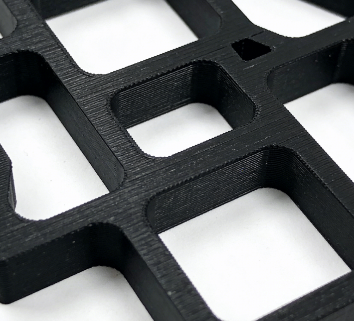
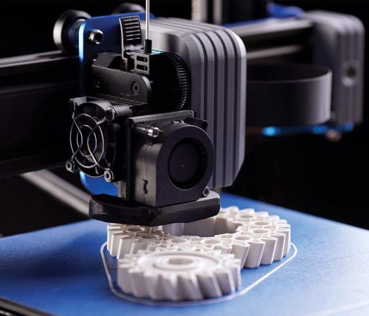
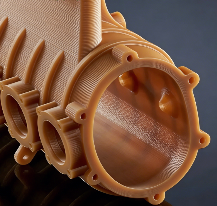
Fused Deposition Modeling (FDM) is a widely used additive manufacturing technology favored for its fast build speed, high dimensional accuracy, and low manufacturing cost. FDM equipment heats and precisely extrudes thermoplastic materials, building layer by layer to form the final part structure. Parts made with this process can be delivered in as fast as 1 day.
KH-TAT's FDM 3D Printing Services relies on the Stratasys Fortus industrial platform, offering build sizes up to 24" x 36" x 36" to meet large-format part manufacturing needs. We also support various general-purpose material options and can flexibly adapt to different FDM or FFF equipment for production.FDM process offers the richest color selection and production-grade thermoplastic system among all 3D printing technologies. Common materials include general-purpose ABS, ASA, and engineering plastics like high-performance polycarbonate and heat-resistant ULTEM, suitable for diverse scenarios from prototype validation to end-use parts.
General Purpose Materials
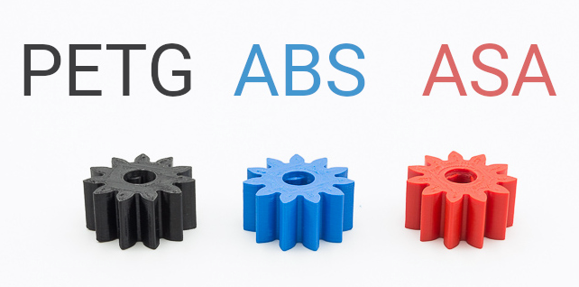
General Purpose FDM Materials Available at Xometry:
| Material Name | Color(s) | Tensile Strength, Yield (XZ MPa-ZX MPa) | Elongation at Break (XZ%-ZX%) | HDT @ 66 psi (°C) | Data Sheets |
|---|---|---|---|---|---|
|
ABS (General Purpose) |
Black, Blue, Dark Grey, Ivory, Red, White |
33 MPa-28 MPa |
10.5%-4.7% |
87 °C |
ABS Data Sheet (Reference Only) |
|
PLA (General Purpose) |
Black, Blue, Red, White |
50 MPa-37 MPa |
2.9%-1.9% |
55 °C |
PLA Data Sheet (Reference Only) |
|
ASA (General Purpose) |
Black, Dark Blue, Dark Gray, Light Gray, Green, Ivory, Orange, Red, White, Yellow |
37 MPa-31 MPa |
9.2%-4.6% |
100 °C |
ASA Data Sheet (Reference Only) |
|
PETG (General Purpose) |
White, Black, Dark Grey, Blue, Red, Yellow |
50 MPa-47 MPa |
5.1% |
68 °C |
PETG Data Sheet (Reference Only) |
|
Stratasys ABS-M30 |
Black, Blue, Dark Grey, Ivory, Red, White |
30.8 MPa-27.5 MPa |
8.1%-1.8% |
104.4 °C |
ABS-M30 Data Sheet |
|
Stratasys ASA |
Black, Dark Blue, Dark Gray, Light Gray, Green, Ivory, Orange, Red, White, Yellow |
32.8 MPa |
5.9%-1.8% |
102 °C |
ASA Data Sheet |
Stratasys material properties are achieved by running OEM materials and parameters on OEM Fortus equipment. Due to a broad material and equipment allowance, general ABS, ASA, PETG and PLA material properties and colors may vary slightly, and datasheets are for reference only. International options are available for generic materials.
High Performance Engineered Materials
High Performance FDM Materials Available at Xometry:
| Material Name | Color(s) | Tensile Strength, Yield (XZ MPa-ZX MPa) | Elongation at Break (XZ%-ZX%) | HDT @ 66 psi (°C) | Data Sheets |
|---|---|---|---|---|---|
|
Nylon 6 CF (Generic) |
Black |
102 MPa-48 MPa |
5.8%-3.7% |
186 °C |
Nylon 6 CF Data Sheet (Reference Only) |
|
Stratasys ABS-CF10 |
Black |
39.4MPa-19.6MPa |
1.6%-1.1% |
100 °C |
ABS-CF10 Data Sheet |
|
Stratasys Nylon 12 |
Black |
49.3 MPa-41.8 MPa |
30%-6.5% |
91.9 °C |
Nylon 12 Data Sheet |
|
Stratasys PC |
White |
93.9 MPa-53.1 MPa |
12%-1.9% |
144 °C |
PC Data Sheet |
|
Stratasys PC-ABS |
Black |
36.5 MPa |
4.7%-1.8% |
117.9 °C |
PC-ABS Data Sheet |
|
Stratasys ULTEM 1010 |
Amber (Natural) |
No Yield |
4.0%-1.1% |
216 °C |
ULTEM 1010 Data Sheet |
|
Statasys ULTEM 1010 CG (Certified Grade) |
Amber (Natural) |
No Yield |
4.0%-1.1% |
216 °C |
ULTEM 1010 Data Sheet |
|
Stratasys ULTEM 9085 |
Black, Tan |
69.2 MPa-No Yield |
5.4%-1.9% |
178 °C |
ULTEM 9085 Data Sheet - Applies to USA Only |
|
Stratasys Antero 800NA |
Amber |
86.7MPa-59.4MPa |
6.1%-2.3% |
158 °C |
Antero 800NA Data Sheet |
|
Stratasys VICTREX AM 200 |
Amber |
60.7MPa-48.9MPa* |
8.3%-3%* |
151 °C (Tg Onset) |
VICTREX AM 200 Data Sheet |
Stratasys material properties are achieved by running OEM materials and parameters on OEM Fortus equipment. Due to a broad material and equipment allowance, Nylon 6 CF material properties and appearance may vary slightly, and datasheets are for reference only.
* VICTREX AM 200 values based on F900 w/SUP8000B Support configuration.
Speciality Materials for Medical or Electronics
Special Purpose FDM Materials Available at Xometry:
| Material Name | Color(s) | Tensile Strength, Yield (XZ MPa-ZX MPa) | Elongation at Break (XZ%-ZX%) | HDT @ 66 psi (°C) | Data Sheets |
|---|---|---|---|---|---|
|
Stratasys ABS-ESD7 (Static Dissipative) |
Black |
35.4 MPa |
3.4%-1.59% |
104.6 °C |
ABS-ESD7 Data Sheet |
|
Stratasys Antero 840CN03 |
Black |
94.9MPa-56MPa |
2% |
149.5 °C |
Antero 840CN03 Data Sheet |
|
Stratasys ABS-M30i (Biocompatible) |
Ivory |
36 MPa |
4.0% |
96 °C |
ABS-M30i Data Sheet |
|
Stratasys PC-ISO (Biocompatible) |
Translucent Natural, White |
57 MPa |
4% |
133 °C |
PC-ISO Data Sheet |
Properties apply to US-based production (Stratasys Fortus FDM).
Common FDM 3D Printing Materials
KH-TAT offers a range of economical rigid thermoplastics widely used in Fused Deposition Modeling (FDM/FFF) processes, compatible with various industrial and desktop 3D printers. Common general materials include ABS, ASA, PETG, and PLA, meeting daily prototyping and functional verification needs.
For applications requiring higher mechanical performance, we recommend Nylon 6 CF (carbon fiber reinforced nylon). This material offers excellent strength, stiffness, chemical resistance, and heat resistance, suitable for structural and functional component manufacturing. Such materials excel in Markforged Onyx series filaments and carbon fiber nylon products from brands like Bambu Lab and Polymaker. Leveraging our extensive printer network resources, KH-TAT can quickly respond to customer needs and deliver popular engineering materials at competitive prices, providing flexible options for customers seeking alternatives to OEM brands like Stratasys.
Available Finishes for FDM Parts

Ready to get started on your 3D printing quote?
Free shipping available for domestic 3D printing orders
Typical Applications of FDM 3D Printing
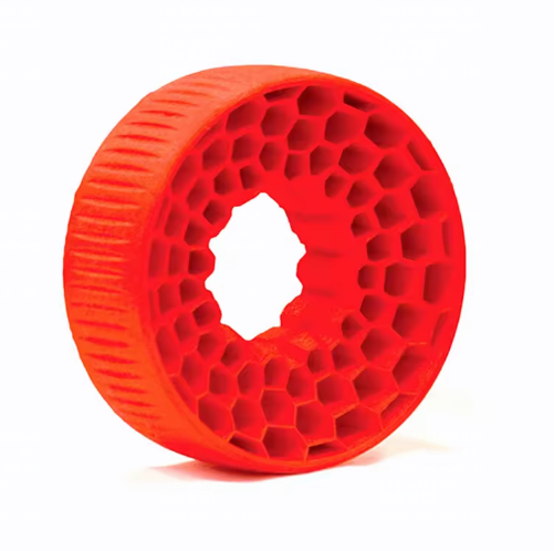
Concept Models
With its rapid response capability, FDM technology allows engineers to quickly obtain physical representations of designs, facilitating early design validation, communication, and iterative optimization.
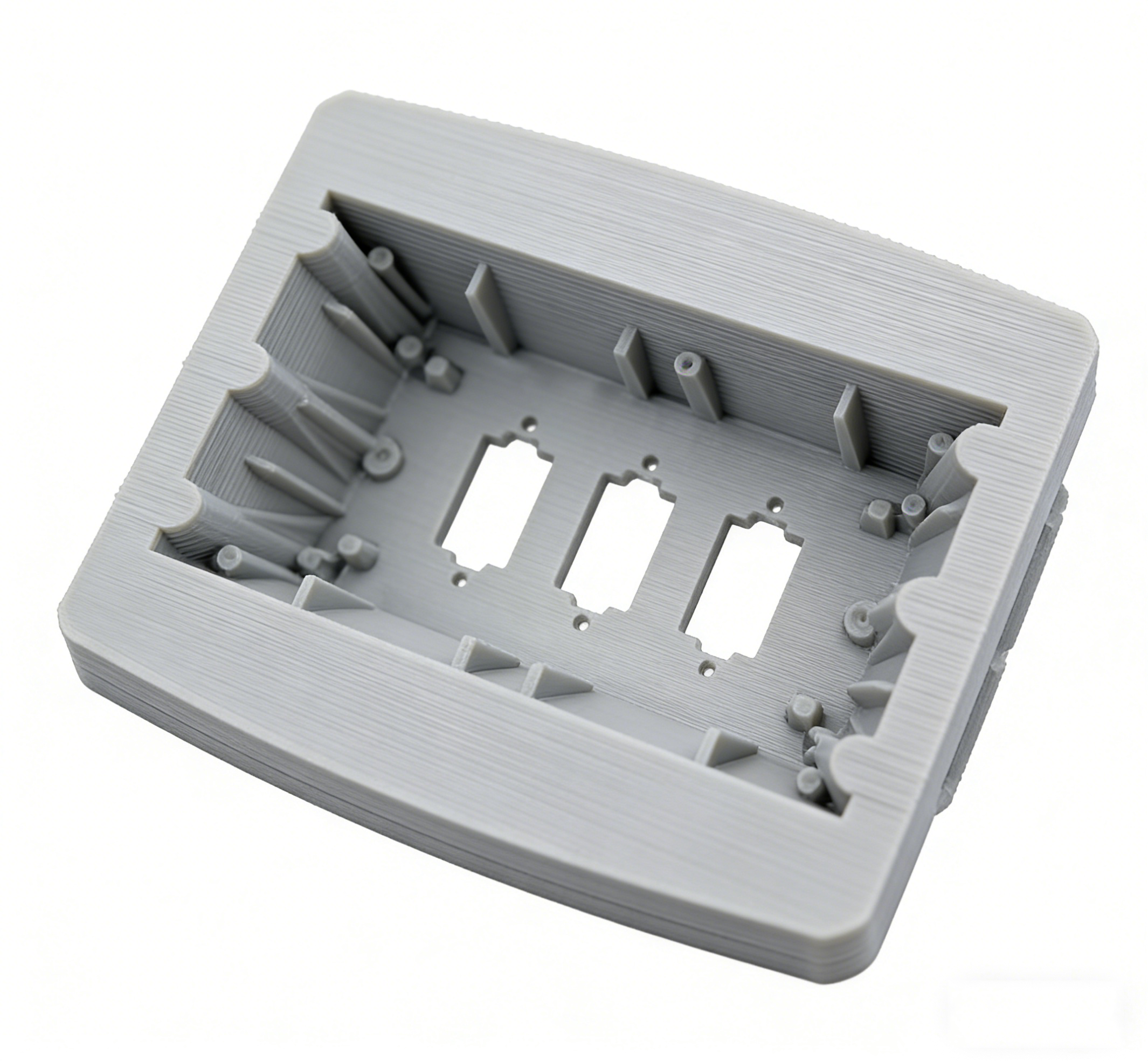
Rapid Prototyping
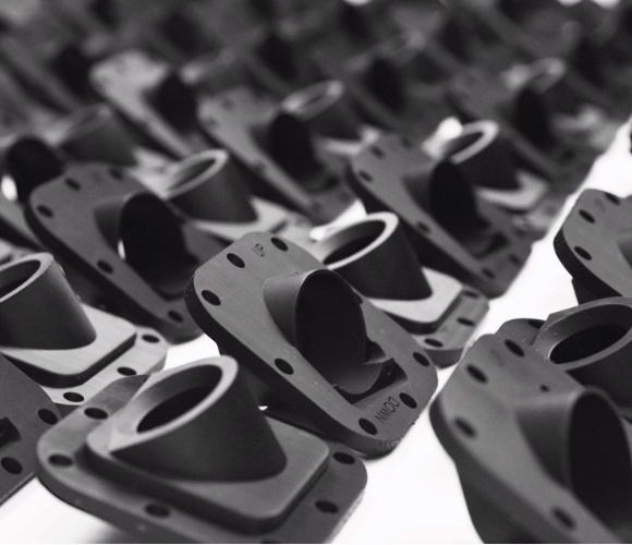
FDM equipment can produce functional prototypes with good durability, capable of withstanding test conditions such as thermal stress, chemical corrosion, and mechanical loads, meeting real-world validation requirements..
Manufacturing Tools
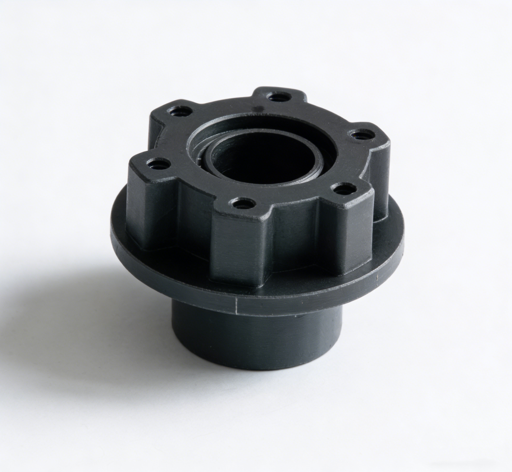
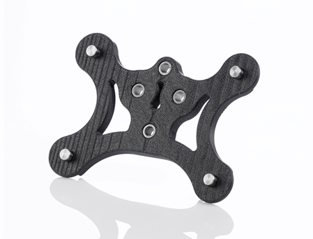
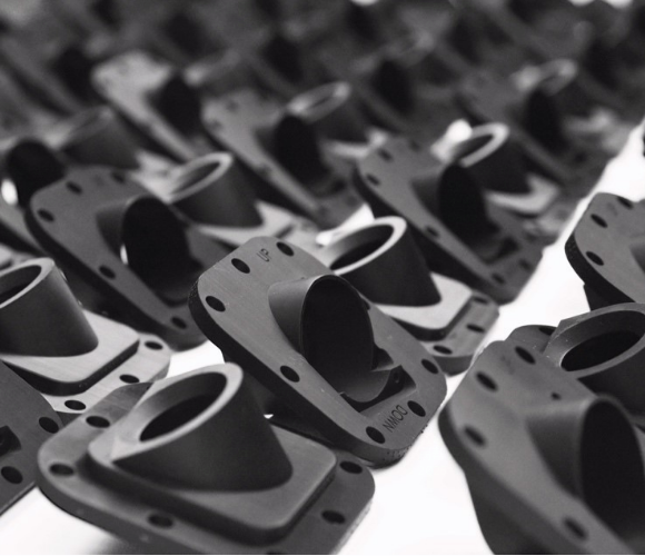
With high-performance engineering materials, FDM is an ideal choice for manufacturing jigs, fixtures, and production aids, replacing traditional metal processing in low-volume production, reducing costs and shortening lead times.
Benefits of Fused Deposition Modeling (FDM)
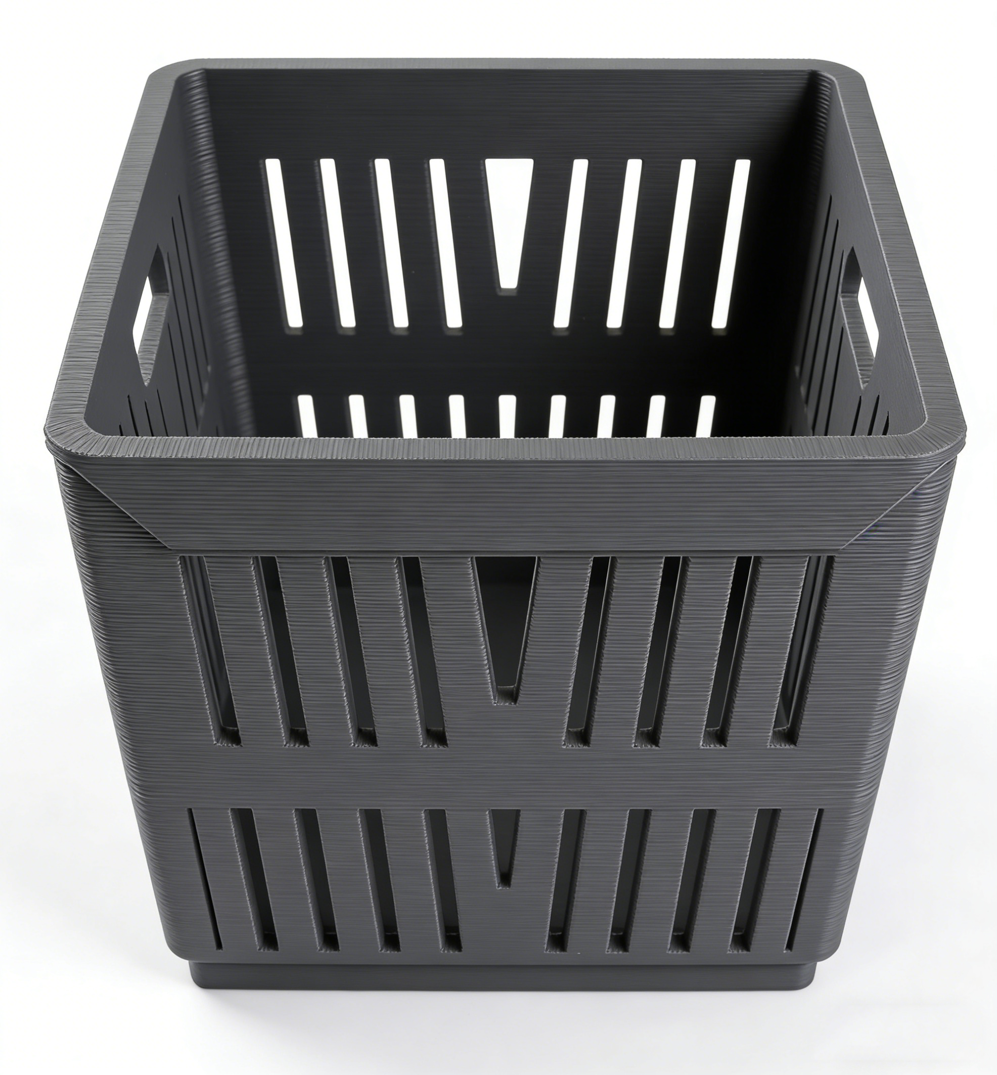
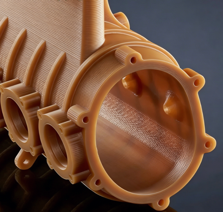
FDM General Tolerances
General Tolerances for FDM 3D Printing
| Tolerance Note | Description |
|---|---|
|
General Tolerance |
+/- a single build layer thickness for the first inch and +/- .002” for every inch thereafter. |
|
Build Size |
Up to 24" x 36" x 36" |
|
Layer Height, less than 16" |
.007" - .010" layers dependent on material |
|
Layer Height, greater than 16" (up to 36") |
0.013" Layers |
|
Minimum Wall Thickness |
0.047"(less than 16"), 0.060" (greater than 16") |
FDM 3D printed parts can be built up to 24" x 36" x 36". Stratasys Fortus 400/450-series machines will produce parts up to 16", and Stratasys Fortus 900MC or F900 platforms are used for parts larger than 16". General-purpose ABS, ASA, PETG, PLA, and Nylon 6 CF may be built on desktop equipment, using generic materials, or both. General tolerances apply before secondary finishing or post-processing unless otherwise specified. To learn more tips about FDM 3D printing, check out our Fused Deposition Modeling (FDM) Design Guide. Applies to US-based production only.
FDM General Tolerances
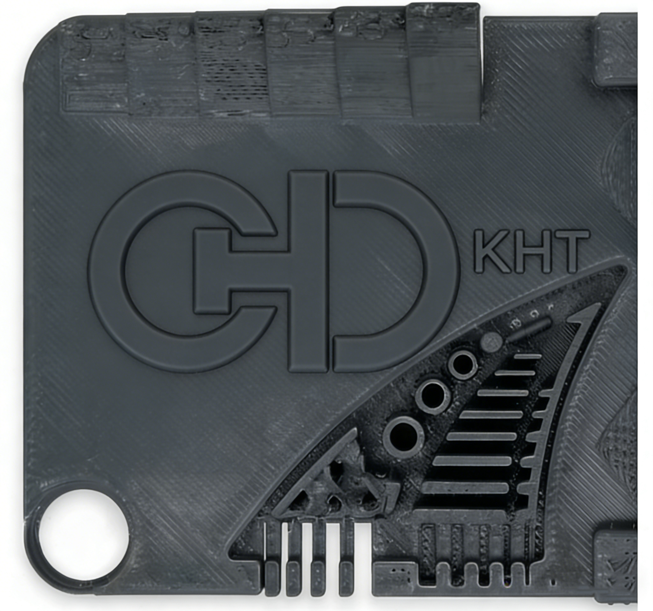
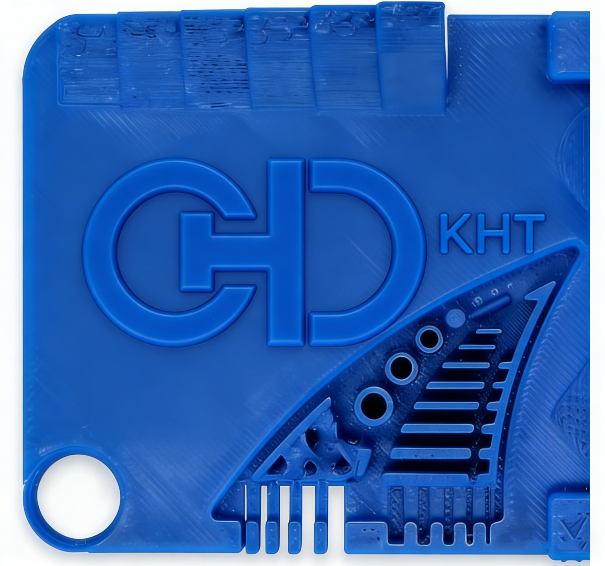
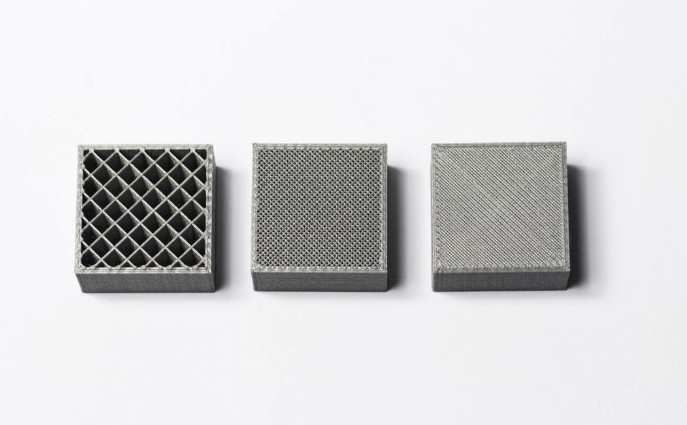
FDM Infill Options
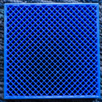
Solid
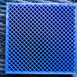
Ultralight
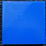
Light
What is Infill?
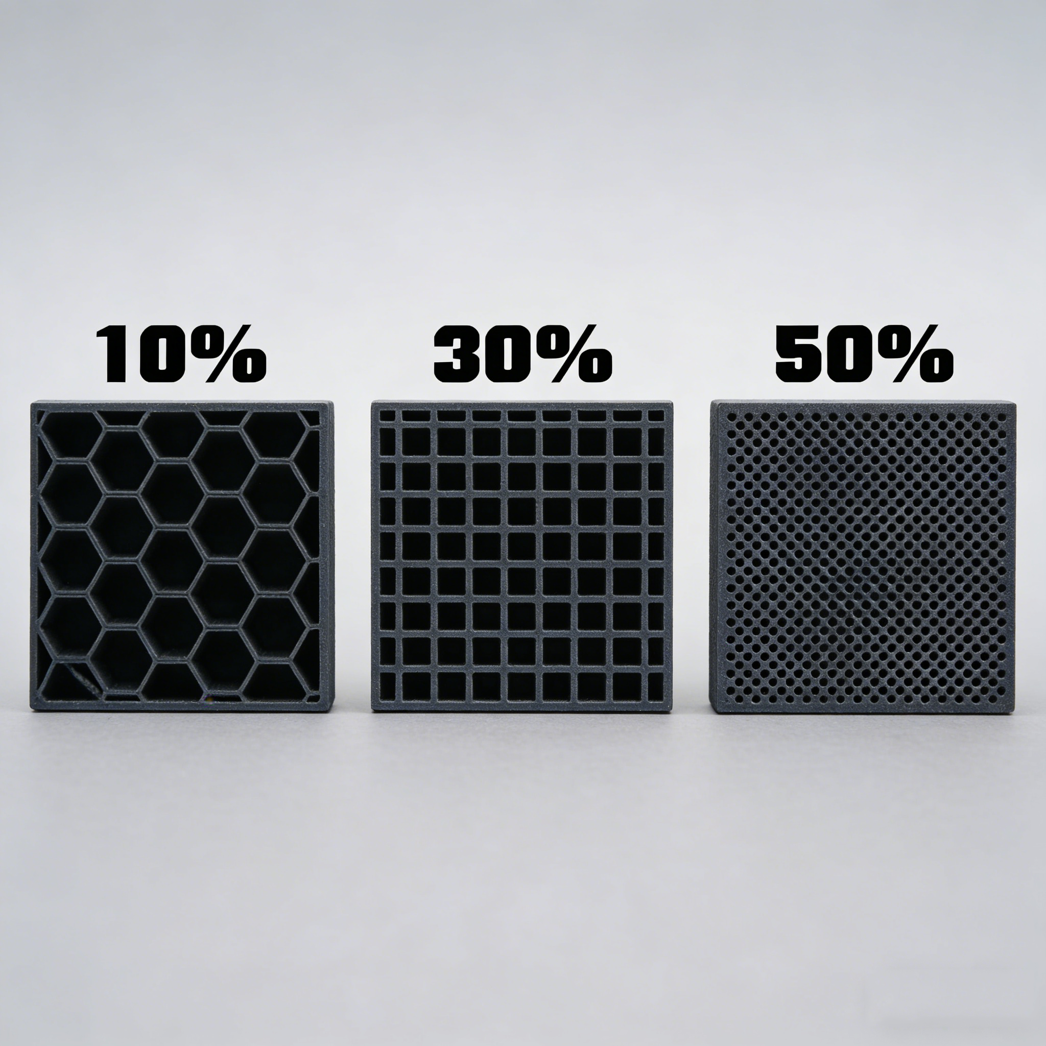
Infill is a characteristic unique to the FDM process. In FDM, an extruder nozzle deposits material along the toolpath, fusing it to previous layers to build a 3-dimensional body. The interior of the volume can be printed as “solid,” but it does not necessarily have to be. The pattern printed inside the contours is referred to as “infill.”
Infill can reduce material consumption and weight and allow for the production of confined volumes. An in-depth article on infill can be read here.
An Overview of the FDM Process
How Fused Deposition Modeling Works
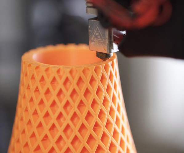
With FDM technology, a spool of the chosen feedstock is introduced to a typical fused deposition modeling system via an extruder, which regulates the feed movement of the polymer to the heater where it melts. This molten polymer is extruded through a nozzle and deposited onto the print bed, also known as the build platform. The extruder, heater, and nozzle are all contained in a printhead, which is attached to a gantry above the flat build platform. This is designed to offer relatively high freedom of motion in the X and Y axes as the material is deposited.
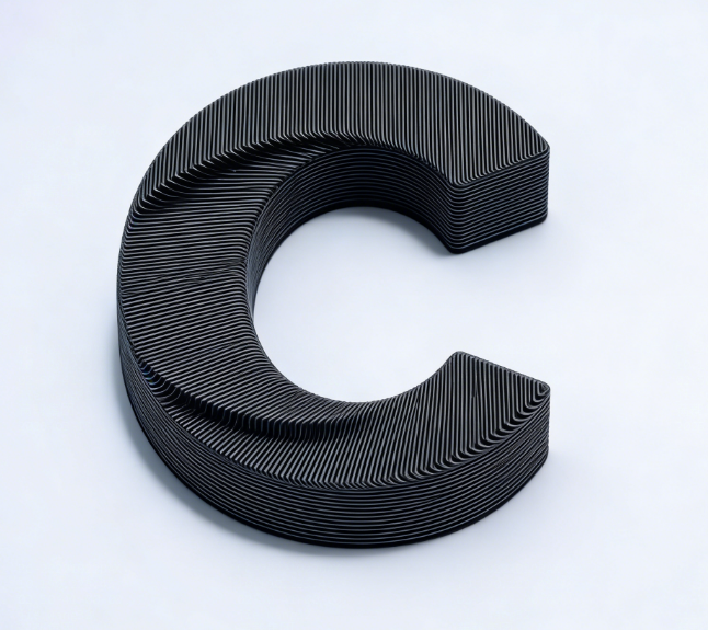
The fused deposition modeling system uses innovative printer software to separate a 3D computer-aided design (CAD) file into individual slices, or cross-sections. Each slice in the file is converted into machine code, which essentially uses the Cartesian coordinate system to determine the path the printer head must follow across the X and Y axes to deposit the first layer of material onto the build platform. Once the bottom layer is complete, the build platform descends by a small amount – relative to the deposited layer thickness – and the printhead repeats the process to deposit the second layer. This procedure is repeated in sequential layers until the part is finished.
Why Choose kh-tat for FDM 3D Printing?

Unlimited Options
Choose from millions of combinations of materials, surface finishes, tolerance levels, marking methods, and certifications to flexibly match your order requirements for truly customized manufacturing.

Easy to Use
No need to handle procurement, project management, logistics, or shipping yourself — we handle everything, parts arrive directly at your door, letting you focus on your core business.

Quality Assurance
KH-TAT is Certified to ISO 9001:2015, ISO 13485, IATF 16949:2016, and AS9100D, ensuring every part meets strict industry standards and quality requirements.